Product Details:
Payment & Shipping Terms:
|
| Body Material: | Stainless Steel: A351 CF8 / CF8M | Trim: | SS304, SS316, Dss Etc. |
|---|---|---|---|
| Stem Type: | Rising Stem, RS | Pressure Rating: | Class 600 / 600# |
| Actuator: | Handwheel, Gear Operated | Flange Ends: | RF, RTJ |
| Applicable Medium: | W.O.G | Other: | OEM Available |
| Highlight: | metal seated gate valve,pressure seal gate valve |
||
| Model | Z40W (stainless steel flanged gate valve) |
|---|---|
| Design standard | API 600 / API 6D |
| Pressure class | ASME Class 600 / 600LB / 600# |
| Size range | NPS 2" – 42" (DN50 – DN1050) |
| Body materials | ASTM A351 CF8 (304) · ASTM A351 CF8M (316) |
| End connection | Double flanged — RF or RTJ (ASME B16.5) |
| Structure | OS&Y rising stem · bolted bonnet · flexible wedge · backseat |
| Operation | Handwheel as standard; bevel gear available for large sizes |
| Inspection & test | API 598 |
| Special options | NACE MR0175 on request |
This Class 600LB stainless steel gate valve is the double-flanged, rising stem (OS&Y), bolted bonnet design with a flexible wedge and backseat. The body, bonnet, wedge and seat ring are cast in ASTM A351 CF8 (304) or CF8M (316); the stem is A182 F304 or F316. Flanged ends are to ASME B16.5 with either raised face (RF) or ring type joint (RTJ) facing; face-to-face dimensions are per ASME B16.10, pressure-temperature ratings per ASME B16.34. Sizes run from NPS 2" to NPS 42". The valve is supplied with a handwheel as standard; a bevel gear operator is available for large sizes on request. The model designation Z40W refers to a stainless steel body with the seat integral with the body material, as distinct from Z40H (carbon steel, hard-faced).
Design and Manufacture: Cast steel gate valve to API 600 or API 6D.
Inspection and Test: API 598, API 600 or API 6D.
End flange dimension: ASME B16.5 (for NPS ≤ 24); ASME B16.47 series A / MSS SP-44 (for NPS > 24).
Face to face and end to end: ASME B16.10.
Pressure-temperature ratings: ASME B16.34.
1. Type: Double flanged gate valves, model Z40W
2. Design: OS&Y, bolted bonnet, flexible wedge design
3. Size Range: 2" to 42" (DN50 to DN1050)
4. Pressure Rating: ASME Class 600 / 600#
5. Materials Available in: Cast stainless steel A351 CF8 / CF8M
6. Various trim materials are available to suit different service conditions
7. Actuator: Manual, handwheel (bevel gear available on request)
8. Special Requirement: NACE MR0175 on request
CF8 (304) vs CF8M (316): CF8 corresponds to AISI 304 stainless steel; CF8M corresponds to AISI 316. The key difference is the molybdenum addition in CF8M, which significantly improves resistance to chloride pitting and crevice corrosion. For seawater, chloride-bearing process fluids, and many refinery and petrochemical services, CF8M (316) is the usual selection, while CF8 (304) is adequate for mildly corrosive media where chlorides are not present. The internals change accordingly: CF8 valves use A182 F304 stems and A193 B8 / A194 8 bolting, while CF8M valves use A182 F316 stems and A193 B8M / A194 8M bolting.
RF vs RTJ at Class 600: RF (raised face) is the standard ASME B16.5 connection and remains the default for non-sour oil and gas, water treatment and general petrochemical service. RTJ (ring type joint) uses a metal ring gasket seated in a machined groove, providing a metal-to-metal seal that is preferred for high-pressure, high-temperature and sour service, and is commonly specified together with NACE MR0175. This valve is available with both facings; the face-to-face dimensions differ between RF and RTJ, as listed in the Class 600 dimension table on this page.
Z40W model interpretation: Z denotes gate valve, 4 denotes the flange connection, 0 denotes the structural form (rising stem, bolted bonnet), and W denotes the sealing surface material — in this case the seat is integral with the CF8/CF8M body material, which is why the designation uses W (stainless steel) rather than H (hard-faced carbon steel). Compared with Z40H (carbon steel, hard-faced), the Z40W is the stainless steel version of the same API 600 rising-stem gate valve. For international specification, the valve is referred to as an API 600 stainless steel gate valve, and the Z40W designation is normally quoted alongside the API standard to avoid ambiguity.
1. Bonnet Gasket Style
Stainless steel + flexible graphite combined gasket is used for Class 600 gate valve.
2. Packing Seal
As usual, flexible graphite is used for packing material. PTFE or combined packing material can also be used if requested by the customer.
3. Body and Bonnet Connection
Class 600LB gate valves are usually connected with bolted bonnet design.
4. Disc Design
NPS ≥ 2 gate valves are flexible wedge gate.
5. Seat
For carbon steel gate valve, the seat is usually forged steel. The seat sealing surface is overlay welded with hard alloy specified by the customer. For stainless steel gate valve, the seat is integral with body, or it can be machined directly after hard alloy welding.
6. Backseat Design
All gate valves have backseat design. In most cases, the carbon steel gate valve is fitted with a renewable back seat. For stainless steel gate valve, the back seat is machined directly in the bonnet or machined after welding.
7. Stem Design
The stem is integral forged design. The minimum diameter of the stem shall be as per the standard requirement.
8. Stem Nut
Usually, the stem nut is made of ASTM A439 D2. It can also be made of copper alloy or other materials if requested by the customer.
9. Operation
Hand wheel or bevel gear box is usually used for gate valve operation.
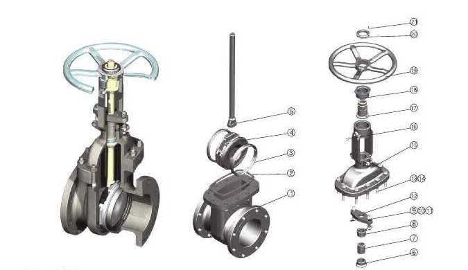
Swipe horizontally to see all materials
| Parts No. | Parts Name | CF8 / 304 | CF8M / 316 |
|---|---|---|---|
| 1 | Body | ASTM A351 CF8 | ASTM A351 CF8M |
| 2 | Gasket | 304 + Graphite | 316 + Graphite |
| 3 | Seat Ring | ASTM A351 CF8 | ASTM A351 CF8M |
| 4 | Gate | ASTM A351 CF8 | ASTM A351 CF8M |
| 5 | Stem | ASTM A182 F304 | ASTM A182 F316 |
| 6 | Backseat Bushing | ASTM A351 CF8 | ASTM A351 CF8M |
| 7 | Packing | Graphite | Graphite |
| 8 | Gland | ASTM A182 F304 | ASTM A182 F316 |
| 9 | Gland Eyebolt | ASTM A193 B8 | ASTM A193 B8M |
| 10 | Eyebolt Nut | ASTM A194 8 | ASTM A194 8M |
| 11 | Eyebolt Pin | 304SS | 316SS |
| 12 | Gland Flange | ASTM A351 CF8 | ASTM A351 CF8M |
| 13 | Bonnet Bolt | ASTM A193 B8 | ASTM A193 B8M |
| 14 | Bonnet Nut | ASTM A194 8 | ASTM A194 8M |
| 15 | Bonnet | ASTM A351 CF8 | ASTM A351 CF8M |
| 16 | Nipple | Carbon steel | Carbon steel |
| 17 | Stem Nut | ASTM A439 D2 | ASTM A439 D2 |
| 18 | Yoke Sleeve Nut | Carbon steel | Carbon steel |
| 19 | Hand Wheel | Ductile Iron | Ductile Iron |
| 20 | Hand Wheel Nut | Carbon steel | Carbon steel |
| 21 | Set Screw | ASTM A193 B7 | ASTM A193 B7 |
Parts No. 9 and 13: original source had "ASTMA193" without a space in some cells — corrected to "ASTM A193" throughout. Parts No. 17 Stem Nut: original source listed "A439 02" in the CF8 column — corrected to A439 D2 to match the CF8M column. Nipple, Yoke Sleeve Nut, Hand Wheel and Hand Wheel Nut are shown as carbon steel / ductile iron in both columns because these parts are not wetted and do not change with the body material.
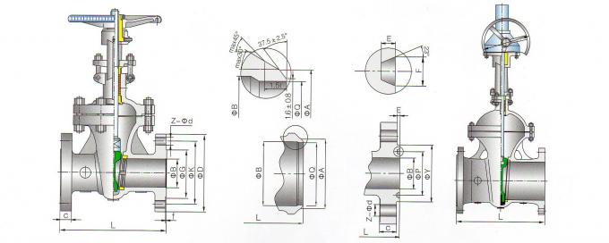
Swipe horizontally to see all dimensions
| NPS | DN | L (RF) | L (RTJ) | B | D | G | f | K | Z-φd | C | RTJ-Y | RTJ-P | RTJ-E | RTJ-F | A |
|---|---|---|---|---|---|---|---|---|---|---|---|---|---|---|---|
| 2 | 50 | 292 | 295 | 49 | 165 | 91.9 | 6.4 | 127 | 8-19.1 | 25.4 | 108 | 82.55 | 7.92 | 11.91 | 63 |
| 2 1/2 | 65 | 330 | 333 | 62 | 191 | 104.6 | 6.4 | 149.2 | 8-22.2 | 28.4 | 127 | 101.6 | 7.92 | 11.91 | 75 |
| 3 | 80 | 356 | 359 | 74 | 210 | 127 | 6.4 | 168.3 | 8-22.2 | 31.8 | 146 | 123.82 | 7.92 | 11.91 | 91 |
| 4 | 100 | 432 | 435 | 100 | 273 | 157.2 | 6.4 | 215.9 | 8-25.4 | 38.1 | 175 | 149.22 | 7.92 | 11.91 | 117 |
| 6 | 150 | 559 | 562 | 150 | 356 | 215.9 | 6.4 | 292.1 | 12-28.6 | 47.8 | 241 | 211.12 | 7.92 | 11.91 | 172 |
| 8 | 200 | 660 | 664 | 201 | 419 | 269.7 | 6.4 | 349.2 | 12-31.8 | 55.6 | 302 | 269.88 | 7.92 | 11.91 | 223 |
| 10 | 250 | 787 | 791 | 252 | 508 | 323.9 | 6.4 | 431.8 | 16-34.9 | 63.5 | 356 | 323.85 | 7.92 | 11.91 | 278 |
| 12 | 300 | 838 | 841 | 303 | 559 | 381 | 6.4 | 489 | 20-34.9 | 66.5 | 413 | 381 | 7.92 | 11.91 | 329 |
| 14 | 350 | 889 | 892 | 334 | 603 | 412.8 | 6.4 | 527.1 | 20-38.1 | 69.9 | 457 | 419.1 | 7.92 | 11.91 | 362 |
| 16 | 400 | 991 | 994 | 385 | 686 | 469.9 | 6.4 | 603.2 | 20-41.3 | 76.2 | 508 | 469.9 | 7.92 | 11.91 | 413 |
| 18 | 450 | 1092 | 1095 | 436 | 743 | 533.4 | 6.4 | 654.1 | 20-44.5 | 82.6 | 575 | 533.4 | 7.92 | 11.91 | 464 |
| 20 | 500 | 1194 | 1200 | 487 | 813 | 584.2 | 6.4 | 723.9 | 24-44.5 | 88.9 | 635 | 584.2 | 9.52 | 13.49 | 516 |
| 24 | 600 | 1397 | 1407 | 589 | 940 | 692.2 | 6.4 | 838.2 | 24-50.8 | 101.6 | 749 | 692.15 | 11.13 | 16.66 | 619 |
| 26 | 650 | 1448 | 1461 | 633 | 1016 | 749.3 | 6.4 | 914.4 | 28-50.8 | 108 | 809.8 | 749.3 | 12.7 | 19.84 | 670 |
| 28 | 700 | 1549 | 1562 | 684 | 1073 | 800.1 | 6.4 | 965.2 | 28-54 | 111.3 | 860.6 | 800.1 | 12.7 | 19.84 | 721 |
| 30 | 750 | 1651 | 1664 | 735 | 1130 | 857.3 | 6.4 | 1022.4 | 28-54 | 114.3 | 917.4 | 857.25 | 12.7 | 19.84 | 772 |
| 32 | 800 | 1778 | 1794 | 779 | 1194 | 914.4 | 6.4 | 1079.5 | 28-60.3 | 117.3 | 984.3 | 914.4 | 14.27 | 23.01 | 825 |
| 34 | 850 | 1930 | 1946 | 830 | 1245 | 965.2 | 6.4 | 1130.3 | 28-60.3 | 120.7 | 1035.1 | 965.2 | 14.27 | 23.01 | 876 |
| 36 | 900 | 2083 | 2099 | 874 | 1314 | 1022.4 | 6.4 | 1193.8 | 28-66.7 | 124 | 1092.2 | 1022.35 | 14.27 | 23.01 | 927 |
| 42 | 1050 | 2439 | 2455 | 1020 | 1403 | 1168.4 | 6.4 | 1282.7 | 28-66.7 | 168.1 | 1080 |
Dimensions in mm. L = face-to-face dimension (RF / RTJ) per ASME B16.10. RF and RTJ flange dimensions per ASME B16.5 for NPS ≤ 24; ASME B16.47 series A for NPS > 24. NPS 38 and NPS 40 are not listed in the original Class 600 dimension series. The RTJ groove dimensions (Y, P, E, F) for NPS 42 are not listed in the original source and are to be confirmed with our engineering team before ordering.
What is the difference between CF8 and CF8M on a Class 600 stainless steel gate valve?
CF8 corresponds to AISI 304 stainless steel; CF8M corresponds to AISI 316. The key difference is the molybdenum addition in CF8M, which significantly improves resistance to chloride pitting and crevice corrosion. For seawater, chloride-bearing process fluids, and many refinery and petrochemical services, CF8M (316) is the usual selection, while CF8 (304) is adequate for mildly corrosive media where chlorides are not present. The internals change accordingly: CF8 valves use A182 F304 stems and A193 B8 / A194 8 bolting, while CF8M valves use A182 F316 stems and A193 B8M / A194 8M bolting.
What does the Z40W model designation mean?
Z40W is a Chinese national standard model designation for stainless steel flanged gate valves. Z denotes gate valve, 4 denotes the flange connection, 0 denotes the structural form (rising stem, bolted bonnet), and W denotes the sealing surface material (stainless steel body material, i.e. the seat is integral with the CF8/CF8M body). Compared with Z40H (hard-faced carbon steel), the Z40W is the stainless steel version of the same API 600 rising-stem gate valve. In international specification, the valve is referred to as an API 600 stainless steel gate valve, and the Z40W designation is normally quoted alongside the API standard to avoid ambiguity.
When should RTJ ends be chosen over RF ends on a Class 600 stainless gate valve?
RF (raised face) is the standard ASME B16.5 connection and remains the default for non-sour oil and gas, water treatment and general petrochemical service at Class 600. RTJ (ring type joint) uses a metal ring gasket seated in a machined groove, providing a metal-to-metal seal that is preferred for high-pressure, high-temperature and sour service, and is commonly specified together with NACE MR0175. This valve is available with both facings; the face-to-face dimensions differ between RF and RTJ, as listed in the Class 600 dimension table above.
Is NACE MR0175 available on this stainless steel gate valve?
Yes, NACE MR0175 / ISO 15156 compliance is available on request. The H2S partial pressure, operating temperature, CO2 content and chloride concentration from your line conditions are needed to confirm the correct material and hardness specification before production. Note that CF8M (316) is often preferred over CF8 (304) for sour service because of its higher resistance to chloride stress corrosion cracking, and the bolting specification is confirmed at the same time.
Contact Person: Mr. Biff Teng
Tel: 86-18066318081


